Alarm Switchboard Module Type 1 (ASM-1)
With the introduction of our new product line (Chameleon+), 2023 (or while supplies last) marks the end of production for legacy Chameleon (EOL Announcement). We will continue to provide technical support on all EOL products. In addition, we will continue to repair the EOL products for as long as replacement parts can be acquired.
Features and Benefits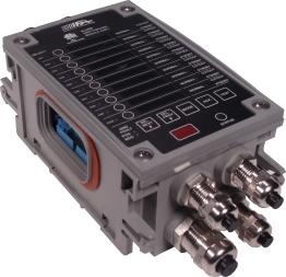
- Ten supervised circuits for alarm monitoring
- Detects open, short, and +/- chassis faults on every channel
- Two solid-state relay outputs to activate alarms
- Ideal replacement for Navy IC/SM panels
- Allows wide range of resistor values to support legacy alarms
- Fully Sealed Enclosure (NEMA 4X, 6, 13 Protection)
- -40°C to +65°C (-40°F to +149°F) Operating Range
- -40°C to +85°C (-40°F to +185°F) Storage Range
- MIL-S-901D Grade A for High Impact Shock (Pending)
- MIL-STD-167B for Vibration (Pending)
- MIL-STD-461E for Electro-Magnetic Interference (Pending)
- Powerful and easy-to-use graphical programming
- Supports Hot Swapping
The Chameleon Alarm Switchboard Module (ASM-1) monitors remote alarm contacts for closure to indicate an alarm condition. The cable from the module to each alarm contact is also monitored for fault conditions such as a wire short, a wire open, and positive and/or negative terminal to chassis ground short. The ASM-1 provides ten (10) such supervisory circuits. The ASM-1 also provides two programmable solid-state relay outputs to activate external notification alarms (i.e., to provide plant operators additional audio or visual cues that an alarm condition has occurred).
With its on-board I/O suite, the ASM-1 can be combined with a power supply module (ACP-1 or DCP-1) and audio visual notification (AVN-1) module to replicate the functionality of a standard Navy IC/SM panel. In contrast to competing solutions that require specific alarm circuit values, the ASM-1 supports a range of resistor values. This flexibility enables the module’s use with a wide variety of legacy installations without the need to change the alarm circuit wiring.
Powered by a 33MHz ARM processor with 1MB of onboard RAM and 1MB of flash memory, the ASM-1 provides sufficient computational power to handle the most demanding applications. The embedded firmware stored in its flash memory is upgradeable: you can rest assured that the hardware investment you make in Chameleon will not become obsolete.
Using Fairmount Automation’s intuitive and easy-to-use graphical programming package (Design Pad) you can develop sophisticated monitoring schemes for the ASM-1 in a matter of hours—even without any prior programming experience. Programming the device entails “drawing” a desired monitoring application using a vast array of configurable function blocks. Once complete, configuration programs are downloaded to the unit via a wireless IR interface.
The ASM-1 provides an integral user-interface for local indication. The ASM-1 front panel provides a suite of LEDs that indicate the status of the supervised circuits. These include three green LEDs per channel to indicate specific alarm states (normal, cutout, or standby), one red LED indicating positive chassis ground fault condition, and one red LED indicating negative chassis ground fault condition. The local panel also includes eight user-programmable three-color LEDs with an associated tag holder for signal labeling, as well as buttons to acknowledge and clear alarm conditions and to test that an alarm and its corresponding indicators are operational.
As with all Chameleon modules, the ASM-1 offers unequaled ruggedness. It is specifically designed for sustained operation in severe environments, including those characterized by extreme shock, vibration, electro-magnetic interference, temperature, and/or humidity. Its fully-sealed enclosure (sealing end-caps not pictured) ensures long-lasting operation in the grimiest settings. In fact, Chameleon modules can operate fully submerged.
| ENVIRONMENTAL CHARACTERISTICS | |
| Operating Ambient Temperature Range | -40°C to 65°C |
| Storage/Transport Ambient Temperature Range | -40°C to 85°C |
| High Impact Shock | MIL-S-901D, Grade A (Pending) |
| Mechanical Vibration | MIL-STD-167B, 0-50Hz (Pending) |
| Electro-Magnetic Interference | MIL-STD-461E (Pending) |
| Facial/Housing Protection | NEMA 1,2,4,4X,5,6,12,12K,13 |
| SUPERVISED INPUTS | |
| Quantity | 10 Channels |
| Sampling frequency | 10 Hz |
| Input range accuracy | +/-10% of point (+/-150Ω min) over temperature |
| Electrical isolation: any input to control circuitry or chassis ground | 400V |
| Maximum expected wire resistance | 52.4Ω per leg (104.8Ω per cable) |
| DIGITAL OUTPUTS | |
| Quantity / Type | 2 Solid State Relays |
| Voltage Rating | 115VAC Inductive or Resistive |
| Maximum Allowed Continuous Current (Any Single Relay) | 1A |
| APPLICATION NOTES | |
| Expected alarm circuit | Resistor R1 in series with parallel circuit consisting of Resistor R2 and Contact Closure K1 |
| Allowable values for R1 | 0-11.5KΩ range; 1.5KΩ typical; must exceed Max Cable Resistance + 500Ω to enable cable short detection |
| Allowable values for R2 | 0-12.0KΩ range; 6.8KΩ typical; can be omitted but disables cable open detection |
| Other requirements on R1 / R2 selection | (1) 500Ω < R1 + R2 < 12KΩ(2) R2 > 1.1 x R1 + Max Cable Resistance + 500Ω |
| ELECTRICAL CHARACTERISTICS | |
| Maximum Power Consumption | 1.5W |
| Real-Time Clock Battery Life (Minimum; No power applied, 25°C) |
10 Years |
| Supported Cable Diameters | Two glands 0.24”-0.47”; six glands 0.16”-0.31” |
| Supported Wire Gauges | 16-28 AWG |
| OPERATOR INTERFACE | |
| Digital Readouts | Ten user programmable three-color (red/yellow/green) LEDs with label holders |
| Channel Select Readouts | One green LED per supervised circuit |
| Alarm Status Readouts | Three green LEDs per supervised circuit; two red LEDs for all supervised circuits |
| Pushbuttons | Channel Select (Previous / Next), Alarm Mode, Alarm Acknowledge, and Test |
| Status Readout |
One three-color (red/yellow/green) LED Indicator |
| IR Wireless Interface |
115KBPS SIR |
| PHYSICAL CHARACTERISTICS | |
| Weight | 2.2 lbs |
| Front Panel Dimensions | 4” W x 6” L |
| Enclosure Height | 3″ H |
The following part numbers can be used when ordering the Alarm Switchboard Module (ASM-1).
| Fairmount Part Number | Description |
| 01012-065 | ASM-1 with Gray Enclosure |
| 01012-365 | ASM-1 with Black Enclosure (without Stuffing Tubes) |
| 11070-200 | ASM-1 Active Board and Gray Cover |
| 11070-250 | ASM-1 Active Board and Black Cover |
| 01014-065 | ASM-1 Full-Size Gray Enclosure with Wiring Hub Assembly |
| 01014-365 | ASM-1 Full-Size Black Enclosure and Wiring Hub Assembly (without Stuffing Tubes) |
| 11071-100 | ASM-1 Wiring Hub Assembly |