Discrete Automation Module Type 2 with Isolated Outputs (DAM-2ISO)
With the introduction of our new product line (Chameleon+), 2023 (or while supplies last) marks the end of production for legacy Chameleon (EOL Announcement). We will continue to provide technical support on all EOL products. In addition, we will continue to repair the EOL products for as long as replacement parts can be acquired.
Features and Benefits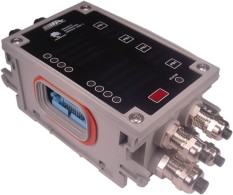
- Logic and Batch Control
- Eight Isolated Hybrid Style Relays for AC Inductive Loads
- Ten Auto-Detecting AC/DC Voltage Inputs
- Integrated User Interface (Push Buttons and Displays)
- Fully Sealed Enclosure (NEMA 4X, 6, 13 Protection)
- -40°C to +65°C (-40°F to +149°F) Operating Range
- MIL-STD-901D Grade A for High Impact Shock
- MIL-STD-167B for Vibration
- MIL-STD-461E for Electro-Magnetic Interference (EMI)
- Powerful and easy-to-use graphical programming
- Supports Hot Swapping
The Chameleon Discrete Automation Module (DAM-2) offers high-performance logic and batch control. The DAM-2 module contains ten digital inputs, eight digital relay outputs, four user-programmable push-buttons, and eight user-addressable tri-color digital readouts that are configured in software. It is powered by an ARM processor with sufficient computational power to handle the most demanding applications. The DAM-2 embedded firmware is stored in its flash memory and is upgradeable: you can rest assured that the hardware investment you make in Chameleon will not become obsolete.
The DAM-2 module offers unique features generally not available in competing controller designs. Its ten universal digital inputs are capable of accepting a broad range of AC and DC signals with no reconfiguration or rewiring required. Its eight digital outputs can be individually configured (in software) for AC or DC operation. The digital outputs offer a unique hybrid design consisting of Form C mechanical relays with contacts shunted by solid-state transistors. This topology offers several advantages over pure solid-state or mechanical contacts:
- In AC mode, hybrid contacts offer dramatically improved endurance as they see virtually no switching arc
- AC hybrid outputs drastically reduce conducted and radiated EMI produced when switching inductive loads by maintaining zero voltage crossing turn-on and zero current crossing turn-off
- AC hybrid outputs offer very low contact resistance (when compared to pure solid state outputs) resulting in small power dissipation across contacts
- In DC mode, mechanical contact life is enhanced thru the use of on-board surge suppression circuitry
The DAM-2 module is available in two wiring configurations for the digital outputs: isolated and banked. In the isolated wiring hub configuration, every relay output has a unique common, normally open, and normally closed terminal connection point. The banked wiring hub configuration provides two power termination groups and arranges the digital outputs into two banks of four relays—the relays in each bank have their common terminal tied together (but each relay maintains unique terminal points for the NO and NC contacts). While the isolated wiring hub configuration provides the most power sourcing flexibility, the banked wiring hub is advantageous in applications that have common power sources by eliminating the need to splice wires. When ordering, use DAM-2ISO for the isolated wiring hub configuration and DAM-2BK for the banked wiring hub configuration.
Each DAM-2 module provides convenient tag holders that can be associated with its digital readouts and push buttons. Multiple modules can be attached to each other to expand I/O capacity and to provide redundant I/O connections. They can also be combined with other Chameleon modules to form a full-featured programmable automation controller. As with all Chameleon modules, DAM-2 units are hot-swappable.
| ENVIRONMENTAL CHARACTERISTICS | |||
| Operating Ambient Temperature Range | -40°C to 65°C | ||
| Storage/Transport Ambient Temperature Range | -40°C to 85°C | ||
| High Impact Shock | MIL-STD-901D, Grade A | ||
| Mechanical Vibration | MIL-STD-167B, 0-50Hz | ||
| Electro-Magnetic Interference | MIL-STD-461E | ||
| Facial/Housing Protection | NEMA 1,2,4,4X,5,6,12,12K,13 | ||
| DIGITAL INPUTS | |||
| Quantity | 10 | ||
| Maximum Allowable Continuous Input Voltage | 200 VDC or 140 VAC RMS | ||
| Maximum Allowable Voltage Spike | 1000V peak 1.2µS x 50µS pulse per MIL-STD-1399 Section 300 | ||
| Logic High Voltage Range | 5-200 VDC or 24-130 VAC RMS 55-500 Hz | ||
| Minimum Input Duration for Logic High Detection | 4 ms | ||
| Logic Low Voltage Range | 0-1 VDC or 0-0.5 VAC RMS 55-500 Hz | ||
| Minimum Input Duration For Logic Low Detection | 56 ms | ||
| Minimum Input Current Required (AC and DC inputs) |
5mA RMS |
||
| Electrical Isolation: Two sets of 5 input banks: Bank to Bank Isolation as well as Digital Input to Digital Input, Control Circuitry or Chassis Ground |
1240 VRMS for 1 minute |
||
| DIGITAL OUTPUTS | |||
| Quantity / Type | 8 Form “C” Hybrid Relays (Electromechanical / Solid-State) | ||
| DC Mode Close Time / Open Time | 5 ms typical (excluding bounce) / 7 ms typical (excluding bounce) | ||
| AC Hybrid Mode Close Time / Open Time | 9 ms typical (excluding bounce) / 19 ms typical (excluding bounce) | ||
| Voltage Rating | 140 VAC Inductive or Resistive, 28VDC Resistive (DC Inductive Loads Require External Clamp) | ||
| Minimum Voltage to Guarantee Contact Conduction | 5V @ 100mA after break-in (silver nickel contacts) | ||
| Typical Contact Resistance | 20 mΩ @ 5A RMS | ||
| Minimum Contact Ratings | |||
| Load: | Operations: | Standard: | |
| 4.4A, 140VAC on the C/O contact 20/2A, 140VAC, PF=0.3 on the N/O contact |
1.0 x 10⁵ 1.2 x 10⁵ |
5 VDE 0435 AC 15 |
|
| Estimated Contact Rating (Hybrid Mode) | TBD Operations | ||
| Maximum Allowed Continuous Current (Any Single Relay) | 4.4 Amps RMS | ||
| Maximum Allowed Combined Current (ALL Relays) | 16 Amps RMS with no single relay conducting more than 4.4 Amps | ||
| NOTE: If any single relay conducts more than 2A, refer to DAM-2 Power Spread Calculator for Allowable Configurations | |||
| Maximum Allowed Inrush Current (Any Single Relay) | 20 Amps RMS for 400 ms on make | ||
| Maximum Allowed Current During Hot Swap (Any Single Relay) | 4.4 Amps RMS | ||
| Inductive Load Minimum Power Factor (AC Only) | 40% | ||
| Electrical Isolation: Any Output to Control Circuitry or Chassis Ground Digital Output to Digital Output | 1240 VRMS for 1 minute 350 VRMS for 1 minute | ||
| ELECTRICAL CHARACTERISTICS | |||
| Maximum Power Consumption | 1.3W + 0.03 W/mA x (current draw from aux. power source) + 0.05 W / relay x (number of relays in use) | ||
| Maximum Allowable Auxiliary Current | 250mA at 24VDC | ||
| Real-Time Clock Battery Life(Minimum; No power applied, 25°C) |
10 Years |
||
| Supported Cable Diameters | Two glands 0.24”-0.47” and six glands 0.16”-0.31” | ||
| Supported Wire Gauges |
16-28 AWG |
||
| OPERATOR INTERFACE | |||
| Digital Readouts | Eight user programmable three-color (red/yellow/green) LEDs with label holders | ||
| Push-Buttons | Four user-programmable on/off buttons with label holders | ||
| Status Readout | One three-color (red/yellow/green) LED Indicator | ||
| IR Wireless Interface | 115kbps SIR | ||
| PHYSICAL CHARACTERISTICS | |||
| Weight | 2.35 lbs | ||
| Front Panel Dimensions | 4” W x 6” L | ||
| Enclosure Height | 3″ H | ||
The following part numbers can be used when ordering the DAM-2ISO.
| Fairmount Part Number |
Description |
| 01012-019 | DAM-2ISO with Gray Enclosure |
| 01012-319 | DAM-2ISO with Black Enclosure (without Stuffing Tubes) |
| 11047-200 | DAM-2 Active Board and Gray Cover |
| 11047-250 | DAM-2 Active Board and Black Cover |
| 01014-019 | DAM-2ISO Full-Size Gray Enclosure with Wiring Hub Assembly |
| 01014-319 | DAM-2ISO Full-Size Black Enclosure and Wiring Hub Assembly (without Stuffing Tubes) |
| 11049-100 | DAM-1ISO/2ISO Wiring Hub Assembly |