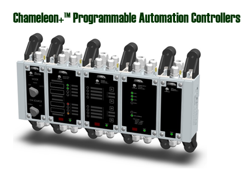
Chameleon Ordering Guide
Step 1: Choose Base Modules in the Node
Select the networking, I/O, operator interface, etc. module(s) that you require for your node. Keep in mind that most modules contain a microprocessor and are programmable — think about how you would like to distribute your field connections and algorithms throughout the node.
Step 2: Select Power Supply Modules
Based on the required power draw from the modules in step 1 and on the available power source, select one or more power supplies for your node. The ACP-1 and DCP-1 can each provide up to 25W of power. Multiple power modules (up to three) can be combined to increase the available power. As a rule of thumb, if you have four or less modules in your node you can safely assume that you only need one power supply. If you are using more than four modules, use the Power Draw Calculator to determine the number of power supply modules required. Add additional power supply modules if you need redundancy.
Step 3: Pick Mounting Method
The Chameleon enclosure supports three different types of mounting methods: Din Rail, Wall/Panel Mount, and Shock and Vibration Mount. Note that you will require (n+1) x 2 number of feet (where n is the number of modules) for your node.
Step 4: Put it all Together
Backplane Cables: Each junction between adjacent modules requires a backplane ribbon cable. The node will require n-1 backplane cables (where n is the number of modules in your node.)
Backplane Terminators: Each node consisting of 2 or more processor modules requires 2 terminators (one at each end) on the node backplane.
End Caps: Each node must contain two end caps to environmentally seal the ends of the enclosure. End caps are reversible so one part can be used on either side.
Chassis Ground Straps: Each power supply will require a chassis ground connection. If you are mounting to a grounded surface then it is recommended that you connect a braid/strap from the external ground stud directly to the surface. There are also chassis ground wire terminals located on the power supply’s wiring hub. If your system is to be MIL-STD 461E qualified then you must add a chassis ground strap on every module in the node.
IrDA Wireless Interface: A link from a PC or laptop to Chameleon is required to (initially) program and interface with the device. In most cases, this link is in the form of wireless IrDA using an adapter. The IrDA adapter plugs into your computer’s RS-232 serial port. You may use a USB to RS-232 converter (and connect the RS-232 IrDA adapter) if a USB connection is desired. Note: Do not use a native USB based IrDA adapter — the adapter must be RS-232.
Wiring Accessories: All field wire connections should be terminated with a ferrule or blade lug before insertion into the terminal block.
Download this MS Excel spreadsheet for a listing of all Chameleon part numbers and accessories.

