Design Pad G4 is a fourth-generation graphical design tool used to program and configure Fairmount Automation’s family of hybrid Programmable Automation Controllers (PAC). It is a Windows-based software package that relies on intuitive drag-and-drop, undo-redo, and cut-copy-paste functionality to enable the rapid development of sophisticated control strategies and automation schemes. It sharply reduces development time by combining the design, testing, and documentation cycle into a single integrated process.
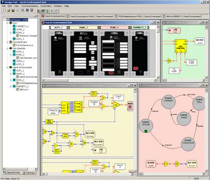
Programming in the Design Pad G4 environment simply involves creating familiar function block and state-transition diagrams in graphic form. The resulting control programs—called schemas—can be compiled into machine-executable form and downloaded into the desired devices over a wireless link or network connection with just a click of the mouse. Future schemas will also incorporate structured text programming (in the standard C language) and ladder-logic diagrams. They will allow all of these languages and constructs to be freely intermixed to suit application needs.
Design Pad G4 provides a comprehensive set of field-proven function blocks, including:
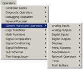
- Controller Blocks (e.g., PID controller, lead-lag)
- Signal Conditioning (e.g. characterizer, limiter)
- Signal Comparator (e.g., high alarm, equality)
- Mathematical (e.g., addition, natural log, sine)
- Logic Functions (e.g., NAND gate, RS flip flop)
- General Purpose Operators (e.g., timer, ramp profile, multiplexer, A/B switch)
- Hardware Access (e.g., analog input, bargraph display, pushbutton)
- Networking Operators (e.g., broadcast, receiver, parameter synchronization)
- Diagnostic Operators (e.g., data recorder, hardware status monitor)
- Text Manipulation (e.g. string constants, concatenation, left, right, etc.)
It places no restrictions on the number of blocks that a program can contain or the manner in which the blocks are interconnected. The links between function blocks can be made by softwire connection or by using signal reference tag names. Once all connections are made, Design Pad automatically determines the execution order of the function blocks, further reducing development time.
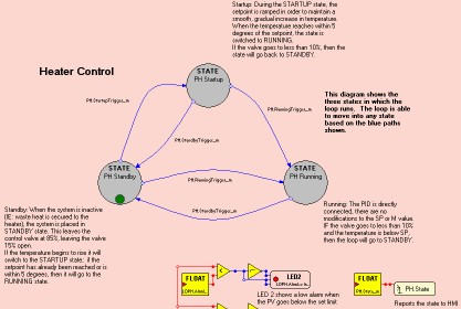
The state-diagramming features allow design engineers to define operational states; to specify what the device should do when it enters, exits, or remains in each state; and to define events that cause transitions from one state to another. The device behavior in each state is programmed in a sub-schema—itself a function block or state-transition diagram. The event definitions that lead to state transitions can be as simple as a digital input signal turning on or can involve a complex set of pre-conditions. The use of state diagrams inherently leads to more robust designs by forcing the segregation of automation tasks into manageable subsystems. Engineers can then focus their design effort on the specific functionality required by each subsystem without the distraction of the system at large. In addition, state diagrams provide a convenient mechanism to encode sequencing operations (they can be structured much like flowchart representations).
Promotes Program Reuse
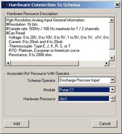
Design Pad emphasizes program reuse by clearly separating the target hardware platform from the control schemas they are to execute. The same schema program can run in any controller module or in any arrangement of modules (provided that the hardware resources referenced by each program are available in the module set). Moreover, the same schema can execute in multiple modules at the same time, yet reference the same or different hardware resources. This hardware independence is made possible by dividing control algorithm development from device configuration. The control programs reference generic hardware function blocks (e.g., analog input signal) that are subsequently bound to specific hardware resources (e.g., analog input channel 1 in the module labeled “Pump C1”).
Device configuration in Design Pad is a fast and easy process that involves selecting the particular hardware platform that will execute each schema program, specifying the characteristics of the physical connections that will be made to the device (e.g., type E thermocouple on analog input 4), and establishing device networks and network signal associations. The hardware platform can be a standalone controller (e.g., FAC2000) or a combination of integrated modules (e.g., Chameleon PAC family).
Integrated Debugging
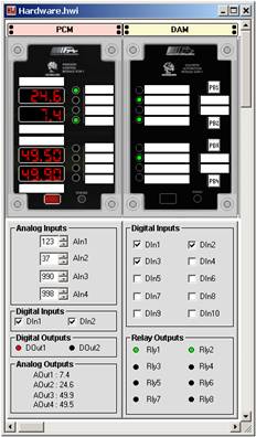
Design Pad G4 provides integrated debugging features that enable program testing as part of the design process, well before a schema ever needs to be exported to a physical device. Its simulation environment includes the very same core run-time code (firmware) that executes in corresponding controller hardware. This assures that if your program works in the virtual world, it will work in the real world. During a device simulation, you can pause, resume, and single-step program execution. You can also manually adjust any input signal that is read by a soft-PAC or monitor any of their output signal states. And, you can interact with virtual user-interfaces that are updated in real-time (e.g., click on front-panel push buttons, verify correct operation of indicators and user text messages, etc.). In addition, you can incorporate soft probes into your schemas to track any internal signal as a simulation evolves. Probed signals can also be streamed to disk for subsequent analysis.
Design Pad G4 is capable of simulating complete controller networks, including concurrent simulations of each device on the network and all the network message traffic between devices. This feature considerably eases one of the most difficult tasks in deploying modern control systems: troubleshooting the coordinated operation of distributed devices.
| Fairmount Part Number | Description |
|---|---|
| 92007-000 | Design Pad G3 Programming Software |
| 92007-100 | Design Pad G4 Programming Software |
| 01004-102 | Chameleon Programming Cable: USB to RS232 to IrDA with Holder |
