- Fire Alarm Control Panels (FACPs) form the information hubs for a Fire Detection System. They provide a modern user interface, signaling loops for detectors/modules, notification circuit, discharge circuit, auxiliary and backup power, and network interfaces in a secure, rugged package.
- They can be used as a stand-alone panel or in conjunction with other Fire Alarm Control Panels.
Features
- Four digital signaling line circuits (SLCs). Each connects up to 254 intelligent devices (total of 1016 SLC devices per panel)
- Detectors support pre-programed activation modes and custom activation thresholds
- Provides a user interface to visually and audibly interact with an operator
- Notification Alarm Circuit (NAC) with synchronization
- Suppression Discharge / Releasing Actuation Circuit (RAC) with actuator health monitoring
- Comprehensive Zone support including pre-alarm, alarm, and discharge with timers, grouping, and cross-zone functionality
- Monitors itself, the devices on the SLC loops, NAC, RAC, and remote panels for event signals and zone activation
- Records all events in a system log
- Re-transmits warning or alarm signals to the other devices in the system with panel collaboration groups
- Panel-to-panel communication over dual-port Ethernet (copper or fiber) with rapid spanning tree rings
- Versatile messaging capability using Ethernet and/or RS-485 using common industrial protocols custom messages for 3rd party data exchange (for example to MCMS)
- All-digital communication between components installed as Class A, B, or X
- Diverse security and information assurance capability
- Enclosure physical entry lock hasp with intrusion detection
- Role based user authentication access control with event logging (includes remote log support for shipboard IDS)
- Data encryption, data wipe, and secure boot
- Security trust zone: System hardware and software validated with restore to trusted state capability
- Provides 42Ah, 28Ah, or 13Ah battery back-up power to attached devices in the event of a loss of primary power
- Powerful graphical configuration and programming environment
- Fully Sealed (IP67 Protection)
- Temperature Range: -30C to +60C (-22F to +140F) Operating, -30C to +80C (-22F to +176F) Storage
- UL-864 Listed (pending)
- MIL-STD-901D for High Impact Shock (pending)
- MIL-STD-167B for Vibration (pending)
- MIL-STD-461E for Electro-Magnetic Interference (pending)
- MIL-STD-1399 300 I/O Compliant (pending)
Click on a Panel Feature Below to Learn More
Control Panel Design Features
Click on the text in the image for more information
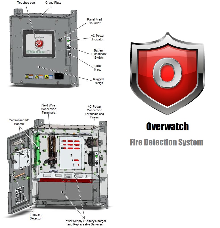
Touchscreen
The Fairmount FDS user interface found on all control and annunciator panels features a large color graphical display that provides the canvas for our screens. It indicates warning and alarm signals as well as provides a graphical user interface for acknowledging signals and performing maintenance and administrative functions. It includes a:
- Ruggedized 10.4-inch, TFT-LCD
- Dimmable ultra-bright backlight allows display to operate in direct sunlight or total darkness
- Multi-finger touch panel (with gloved hand support) allows users to interact using familiar gestures such as swipe to scroll or pan and tap to select
CLICK HERE TO SEE DETAILS ON THE INTERFACE SCREENS
Rugged Design
The FACP is housed in an IP67 watertight enclosure and supports operating over a wide temperature range from -30C to 60C. It is designed and tested for high impact shock, vibration, and electromagnetic interference.
Gland Plate
The panel is supplied with a blank gland plate intended to be customized by the customer to match the interface requirements for a particular installation. The gland plate is constructed from 14 Gauge (5/64”) stainless steel and secured with #8-32 stainless steel screws. Note that two of the screws are ‘security screws’ and can only be installed or removed from the inside of the panel.
Panel Alert Sounder
Alert sounder audibly annunciates new warning and alarm events using distinct tones for each type of event.
AC Power Indication
Bright LED indicator alerts users that primary power is available to the control panel
Battery Disconnect Switch
Monitored battery disconnect toggle switch (protected from inadvertent operation) connects/disconnects the batteries from the power supply and battery charger during maintenance
Lock Hasp

The Fire Panel can be secured with a lock or tamper seal using the lock hasp feature. The hasp design allows a standard U.S. CID A-A-59486-1 padlock to hang freely and includes a mounting bolt for a lock retention chain.
The lock hasp is part of the panel’s suite of cyber security features.
AC Power Connection & Fuses
Color-coded AC power terminals support connection to grounded and ungrounded MIL-STD 1399 compatible shipboard power systems. Fuses can be replaced without the need of tools.
Field Wire Connection Terminals
Power-limited field connections connect to these terminals. The terminals feature spring loaded quick-disconnect style connections for easy wiring. Field connections include:
- Four signaling line circuits SLC loops
- Class A, B, or X
- Powers and communicates with 254 intelligent addressable devices per loop (1016 devices per panel)
- Notification Appliance Circuit (NAC)
- Class A or B
- Synchronization
- Releasing Actuation Circuit (RAC) with supervised health monitoring of actuator coil
- Two Auxiliary Power Sources
- RS-485 Networking (Note: Ethernet Network attaches directly to Control Board)
Control and I/O Boards
The TS1 Control Board (part of the touchscreen assembly) contains the main system processor with associated volatile and non-volatile memory that together execute the software program required for panel’s operation. The non-volatile memory stores the configuration files, panel firmware, and system log.
Two Ethernet network ports can be used to communicate with, monitor, and control other panels or remote systems. The TS1 Control Board also contains a touchscreen driver, intrusion detector interface, and an independent sounder circuit.
The TS1 Control and I/O boards interact via a board-to-board interface that allows the main processor to access I/O functionality. The I/O board operates four SLC loops, a notification appliance circuit (NAC), a fire suppression releasing actuator circuit (RAC), and battery backed-up auxiliary power (Aux Pwr) outputs.
Intrusion Detector
All panels include an internally-mounted intrusion detector to sense when the panel enclosure is opened. When activated, an intrusion event is indicated on all system user interfaces and stored in the log file.
The detector is part of the panel’s suite of cyber security features.
Power Supply / Battery Charger and Batteries
Power supply and battery charger converts fused AC input power to supply continuous DC power to FACP circuits from either the primary AC power or internal sealed lead-acid batteries.
Multiple battery capacities are available (13 Amp-hour, 28 Amp-hour, or 42 Amp-hour) and should be selected based on the anticipated load on the system.
Product Specifications
|
FACP ENCLOSURE |
|
|
Input Power |
115VAC
+/- 15%, 50-60 Hz, 3.2Amps |
|
Rechargeable
Battery Circuit |
Voltage: Two 12V batteries in series Type:
Sealed Lead Acid Ampere-Hour (Ah): 13Ah to 42AhCharging: 2A +/- 10% |
|
Mounting |
Four
3/8-inch diameter, 16 threads-per-inch (tpi), grade
5 bolts (no bulkhead foundation needed) |
|
Dimensions |
20” H x 20” W x 9” D (the height is
23” when including mounting tabs) |
|
Environment |
-30°C
to +60°C (-22°F to +140°F) Operating, -30°C to +80°C (-22°F to +176°F)
Storage Fully Sealed (IP67 Protection) |
|
Weight |
75 pounds including 2×13 Amp-hour batteries,
or 102 pounds including 2×28 Amp-hour batteries, or 126 pounds including 2×42
Amp-hour batteries |
|
Security |
Enclosure
physical entry lock hasp with intrusion detection |
|
|
|
|
SIGNALING LINE CIRCUITS (SLC) |
|
|
Quantity |
4
independent loops |
|
Capacity |
Addressable devices per loop: 126
legacy devices (504 total per panel)254 Core Protocol devices (1016 per
panel) |
|
Network Types |
Class
A, B, or X |
|
Rating |
Special application, power-limited, and
supervised |
|
Output Power |
400mA; 24V,
28V; DC Max line impedance: Device types and quantity attached will determine
maximum impedance. |
|
Cable
Gauge |
14 AWG 16 AWG 18 AWG 18 AWG 2XSW-1 (MIL
DTL 24640-16E) |
|
Max Cable Length |
12000ft
(dependent on devices, cable, and SLC voltage setting) |
|
|
|
|
PANEL NOTIFICATION APPLIANCE CIRCUIT (NAC) |
|
|
Quantity |
1
circuit |
|
Network
Types |
Class A or B |
|
Rating |
Dual-rated,
power-limited, and supervised |
|
Output
Power |
24VDC, 1A either special application or
regulated depending on synchronization |
|
Line Impedance |
Max
line impedance: Device types and quantity attached will determine maximum
impedance. |
|
Cable
Gauge |
14 AWG 16 AWG 18 AWG 18 AWG 2XSW-1 (MIL
DTL 24640-16E) |
|
Synchronization |
Built-in
Wheelock |
|
|
|
|
SLC NOTIFICATION APPLIANCE CIRCUIT (SLC NAC) |
|
|
Quantity |
NAC
connected to addressable SLC Sounder Control Module. Dependent on SLC
circuit and AUX circuit capacity. |
|
Network
Types |
Class A or B |
|
Rating |
Dual-rated,
power-limited, and supervised |
|
Output
Power |
24VDC, 1A either special application or
regulated depending on presence of DSM for synchronization |
|
Line Impedance |
Max
line impedance: Device types and quantity attached will determine maximum
impedance. |
|
Cable
Gauge |
14 AWG 16 AWG 18 AWG 18 AWG 2XSW-1 (MIL
DTL 24640-16E) |
|
Synchronization |
Requires
Wheelock DSM installation directly attached to SLC Sounder Control Module |
|
|
|
|
RELEASING ACTUATION CIRCUIT (RAC) |
|
|
Quantity |
1
circuit |
|
Network
Types |
Class B |
|
Rating |
Special
application, power-limited, and supervised |
|
Output
Power |
24VDC, 1A |
|
Cable Gauge |
14
AWG 16 AWG 18 AWG 18 AWG 2XSW-1 (MIL DTL 24640-16E) |
|
|
|
|
AUXILIARY POWER (AUX) |
|
|
Quantity |
2
circuits |
|
Rating |
Dual-rated, power-limited, and
supervised* * Only SLC NAC, Annunciator, and Portable Annunciator connections
will detect loss of Aux power. |
|
Output Power |
Regulated
24V 1A, special application 24V 3A |
|
Cable
Gauge |
14 AWG 16 AWG 18 AWG 18 AWG 2XSW-1 (MIL
DTL 24640-16E) |
|
ETHERNET COMMUNICATIONS |
|
|
Quantity |
2 x
10/100 Mbps circuits with ground fault detect |
|
Network
Connections |
2 internally switched ports as: Copper/Copper,
Copper/Fiber, or Fiber/Fiber Copper is RJ45 Fiber is: LC, Multimode, 1310 nm,
or ST, Multimode, 1310 nm (with optional conversion kit) |
|
Network Types |
Class
A, B, or X |
|
Rating |
Power-limited and supervised |
|
Topology |
Ring
(pending) or Bus |
|
Panel-to-Panel |
Supported |
|
Protocols |
EtherNet/IP Client and/or Server, Modbus
TCP/IP Client or Server, SNMP, Custom TCP/IP or UDP Messaging |
|
RS-485 COMMUNICATIONS |
|
|
Quantity |
2-Wire Isolated
RS-485 Interface with Selectable On-board Biasing and Termination |
|
Network
Type |
Class B |
|
Rating |
Power-limited
and supervised |
|
Max
Baud Rate |
Up to 1 Mbit / Second |
|
Biasing |
510
Ω high and low |
|
Termination |
120 Ω |
|
Network Load / Drive |
Panel
is 1/8 unit load. Can drive up to 7 unit loads
in bus topology. |
|
Panel-to-Panel |
Not supported |
|
Protocols |
Master
or Slave Modbus RTU/ASCII, Master or Slave FairNET,
and Custom ASCII or Binary Messaging |
|
FDS SYSTEM |
|
|
Panel-to-Panel |
Up to
30 panels and annunciators (max 20 control panels) |
|
Max
addressable Devices |
Up to 8,000 (across all panels)Up to 504 (legacy) / 1016 (Core Protocol) (single
panel) |
|
System Log Capacity |
100,000
entries minimum |
|
Event
List Capacity |
2,000 entries |
|
Zone support |
Includes
pre-alarm, alarm, and releasing with timers, grouping, and cross-zone
functionality. Detectors support pre-programmed activation modes and custom
activation thresholds |
|
Max
Number of Zones |
200 entries |
|
Security |
Intrusion
detection, Role based user authentication access control with event logging
(includes remote log support) Data encryption, data wipe, trust groups, and
secure boot |
