Design Pad has the ability to perform simulations of the system to verify configuration and operation prior to installation. The simulation is an accurate representation of the FDS and much of the same software running on real panels is utilized. Simulated panels contain an identical touch screen interface as a real panel, all field devices are emulated (including the ability to put devices into an alarm or trouble state), and there exists a simulated panel-to-panel network for multi-panel systems. Simulation modes include the ability to mix simulated panels with real panels that use real or emulated field devices.
Elements of the Simulation
Panel Hardware Interface
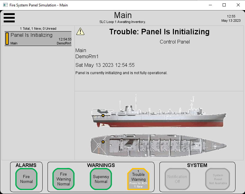
The Panel Hardware Interface screen shows an identical representation of a real panel with full GUI functionality. The interface accepts input from a mouse or computer touch screen to recreate the same tap-to-select and swipe-to-scroll gestures as found on a real panel’s touch panel. The sim panel interacts with other panels in the system over a network. All inputs and outputs (SLC devices, NAC, RAC, etc.) are simulated in the System Emulator.
System Emulator
The System Emulator screen is the main control panel for the simulation. It can be used to set the desired networking and panel hardware window mode, start and stop simulated panels, activate devices to introduce alarms and warnings, and create faults.

Networking Modes
Virtual and Real modes are available for simulation networking:
- Virtual – Network data packets stay within the simulation computer in a shared memory representation of the network
- Real – Network data packets are sent to the simulation computer’s Ethernet network adapter and can interact with other devices (real or simulated) on the network
Simulation Modes
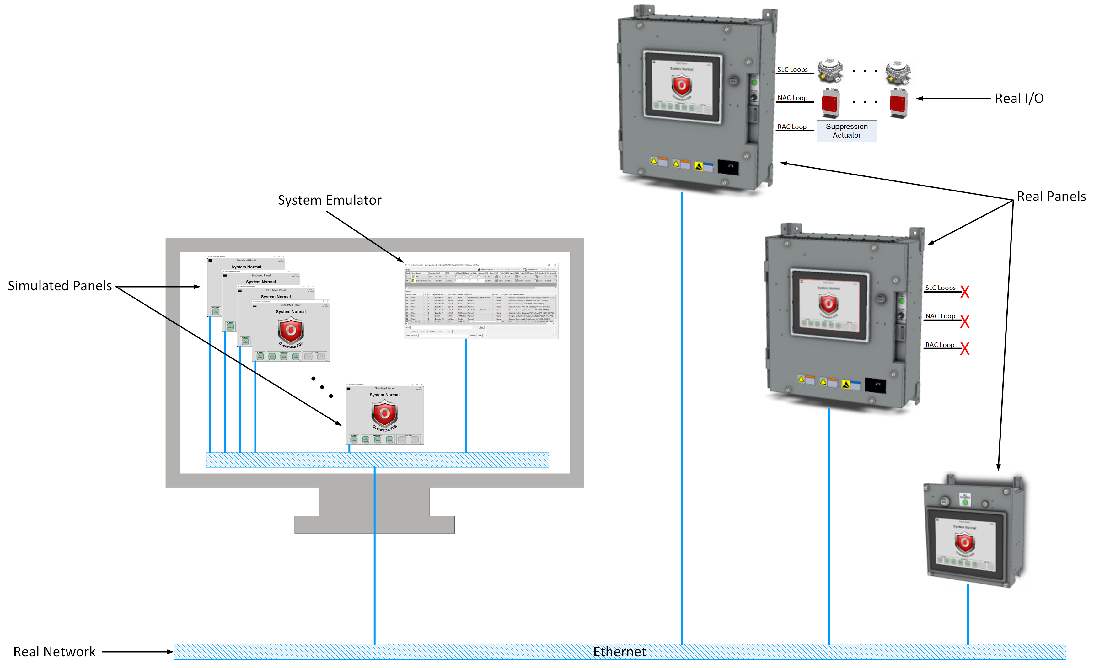
Multiple modes of simulation are available including full-virtual offline simulation, full-real panel system with simulated I/O, and mixed-mode simulation that combines simulated and real panels with simulated and real I/O.
Full-Virtual Simulation
All panels and field input / output devices in the system are simulated. All simulation components communicate over a simulated network for panel-to-panel communication and System Emulator interaction.

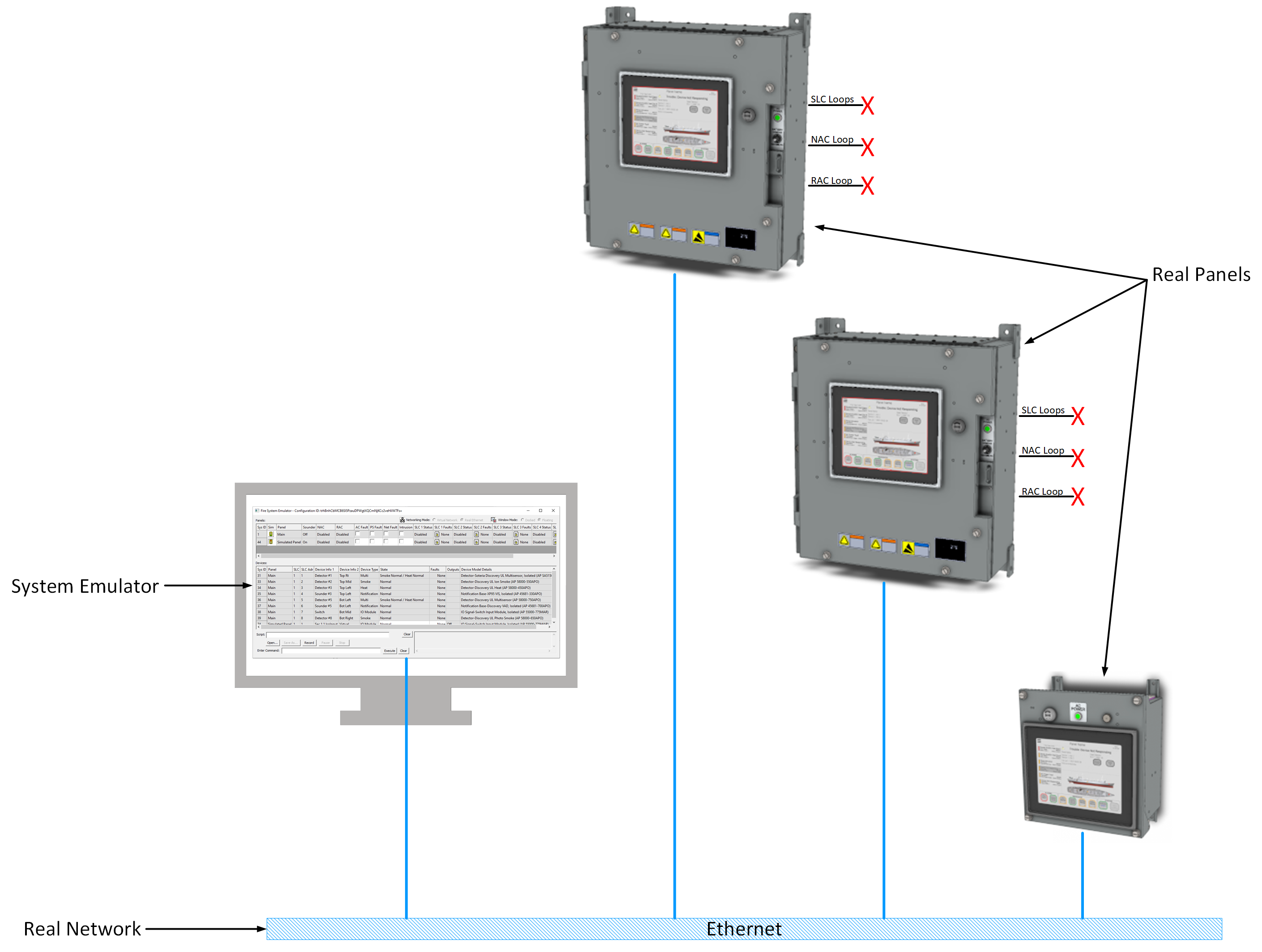
Full-Real Panel System with Simulated Inputs and Output
This mode allows real panels to be used, but instead of connecting to real I/O devices (detectors, notification appliances, releasing actuators, etc.), these panels connect and respond to device states as set in the System Emulator. Any existing field devices that are wired to the panel can remain connected, but they are ignored in favor of the System Emulator. Note that these panels show a prominent red warning banner around the GUI interface to ensure the system is not deployed in this mode.
Mixed-Mode Simulation
Mixed-mode simulation is a free form combination of Full-Virtual, Full-Real with Simulated I/O, and Real Panels with Real I/O. It allows the designer to test their full system configuration using a limited set of real panels and limited set of real I/O.